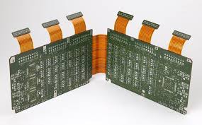
flex PCBs accommodate for dynamic mechanical loads
Unlike rigid PCBs, which are typically surrounded by copper and prepreg, flex PCBs feature an entire layer stack that’s composed of flexible plastics. Polyimide is the most common choice, but PEN, PTFE, and Aramid can also be used. In addition to being highly flexible, these materials are very tough (they can’t be torn or noticeably stretched), tolerant of multiple solder reflow cycles and relatively stable in temperature variations.
flex pcb must accommodate for dynamic mechanical loads, including vibrations and shocks. To do this, they’re built to withstand tensile and compressive stresses along the bending axis, with stress being more concentrated on the outer layers of the flexible section. This is a significant challenge to overcome when designing a flex circuit, but by following a few basic design guidelines it can be done.
One way to reduce the stresses in a flex PCB is to use a thicker overall flexible coverlay. This will prevent tensile shear stress from bunching the surface layers of the coverlay around the neutral bending axis and increasing the amount of compressive shear stress on the signal traces. It’s also important to stagger the trace layers. This will keep the ground mesh layer from being under the signal layers and reducing the chance of failure in the case of a dynamic load.
How do flex PCBs accommodate for dynamic mechanical loads?
Another way to reduce stress is to avoid putting any vias in the bend region. Vias are like little I-beams that act to stiffen the flex and create tensile stress when it’s bent against its will. Leaving them in the bend region will create a stress concentration at that point and likely cause it to fail.
By avoiding any vias in the bend region, a flex circuit can be made much more resilient. However, this may require the engineer to place a connector at the end of the flex section. This could be an issue if there’s a long lead-out or a large gulf between the connector and the edge of the board. In this case, a zero-insertion force (ZIF) connector might be the best option.
Other special requirements to consider include adding what’s called a Stiffener, which is a layer of a rigid material (can be FR4) added to specified areas of the flex PCB to increase overall thickness. This will reduce stress in those regions, but it will also increase the cost. Lastly, some manufacturers offer electrical testing to ensure that the flex circuit is working properly and is free of any faults that might have occurred during manufacturing. This is a useful service, but it will add to the overall cost of the PCB.